POCSAG encoder and modem.en
This page documents the POCSAG encoder Perl module POCSAG::Encode, the Arduino-based bit-banger modem used to drive FSK transmitters with the POCSAG data generated by the encoder, and the POCSAG::PISS perl module used to communicate with the bit-banger modem.
The encoder module should work on all operating systems which have a Perl interpreter available. The modem driver uses the Device::SerialPort module to talk to the modem, which might not be usable on all platforms. I've only tested this on Debian Linux, Ubuntu and Mac OS X Snow Leopard (10.6), and other Unixes should be easy to do.
FAQ: The software for Arduino just sends bits of FSK data out. The POCSAG encoding magic is done by the POCSAG::Encode module, the Arduino is just acting as an interface board here!
Background
We got hold of some Tecnomen HiQ 1000 paging transmitters. Then we bought some programmable paging receivers from Ebay (they're cheap now). And we can run the transmitters on an amateur VHF frequency. But we needed a way to drive the transmitters.
We found source code for a microcontroller-based POCSAG encoder. It would take in a message from the serial line, encode and transmit it. But it could only transmit short messages (POCSAG allows sending pretty long ones), and it would only transmit a single message at a time, which is very inefficient, because the preamble and synchronisation required in the beginning of each transmission is very long when compared to a single short message.
There was also a DOS program to send POCSAG. Needless to say, DOS is a bit out of the question for a networked transmitter solution.
So, something else was needed. And here it is.
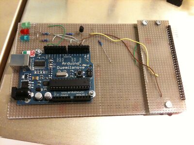
Here's a Youtube video of the Tecnomen paging transmitter with the Arduino modem prototype board - transmitting POCSAG messages successfully using the software available here.
Encoder module
I've implemented a POCSAG encoder in Perl, and packaged it in a proper Perl module, POCSAG::Encode. It's available on the CPAN. It takes in a bunch of text messages, and returns a binary string which should be transmitted, bit-by-bit, using an FSK transmitter at 512 bit/s. The string does not include the mandatory preamble (alternating 1's and 0's), which is generated by the modem to save buffer space. It also returns any messages which did not fit in the transmission (which has a limited length, depending on the buffer size of the modem), so that they can be put in the next transmission.
It can be used with the modem described here, or using some other software which can turn on a transmitter, and transmit the preamble and the encoded messages synchronously at 512 bit/s, 1200 or 2400 bit/s. I've only tested 512 bit/s with this modem, though.
It's not very highly optimized yet, but it tries to do some message order sorting to reduce the amount of idle codewords needed in each transmission.
The module comes with POCSAG::PISS, which contains an interface to talk to the POCSAG modem described below over an serial/USB line. The protocol is, in spirit, much like the KISS (Keep It Simple Stupid) protocol used on AX.25, but for POCSAG use (POCSAG Is Simple, Stupid).
Modem
The reference modem for this POCSAG transmitter was implemented on top of an Arduino Duemilanove microcontroller board. The board design is open-source, and boards are available from a large number of suppliers around the world, from small local electronics shops and from the web, with prices ranging from $25 USD to 30€. The newer Arduino Uno has been tested and found to work, too, the only difference is that the FTDI USB serial chip was replaced with an ATmega8U2 chip. Get a board with an Atmega328 microcontroller - the extra memory is useful here. It's also possible to buy just the Atmel Atmega328, put it on a board of your own design (or a breadboard) and save some components and money, if you wish to spend some additional time for that (or just happen to enjoy that sort of thing). It might make sense for larger batches. Instructions here, here and here.
The traditional method to transmit synchronous FSK from a PC computer was to twiggle the handshaking lines (RTS/CTS/DTR...) of serial ports, or the I/O pins of the parallel port. That was easy in MS-DOS, but in proper operating systems that typically requires writing a kernel driver. And your average computer no long has serial or parallel ports. The Arduino board has an USB port, an FTDI USB-serial chip behind it, and a microcontroller which can be programmed over the USB. No programmer device required - and the same USB port can be used for communicating with the modem software. It also has a good amount of I/O pins which can be used to communicate with the FSK transmitter.
The modem software on the Arduino waits until the channel is clear (by watching the received FSK), keys the transmitter, and simply sends the bits out through the transmitter's TX data (FSK in) pin. It currently has the usual txdelay and txtail settings hard-coded in the source code. It sends a report back to the host software when the burst string has been received by the modem, and when it has been transmitted, so that the host knows to send the next burst.
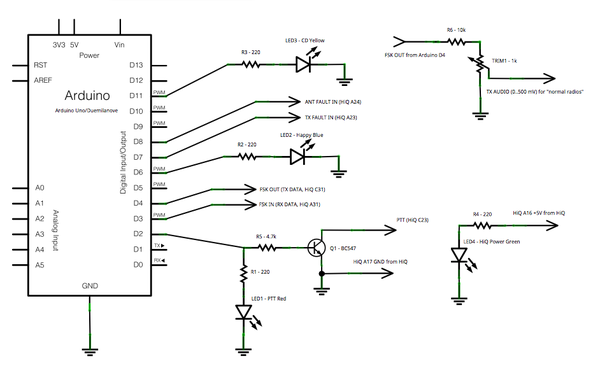
Hooking up the arduino with the transmitter
#define pttPin 2 // PTT, high = ON
#define fskOutPin 4 // drives FSK on the transmitter
#define fskInPin 3 // received FSK, do not change - must have an interrupt (see below)
#define happyLedPin 6 // happy led output, do not change - must have PCM
#define txFaultPin 7 // TX fault signal input, low = FAULT
#define antFaultPin 8 // ANT fault signal input, low = FAULT
#define cdLedPin 11 // Carrier Detect led output
#define ledPin 13 // led pin on the arduino board itself
The pin ordering can be altered by modifying the source code, but the happy led needs to be run using a PCM pin, and the interrupt is only available on a few pins.
The Tecnomen transmitter uses TTL level I/O, which conveniently matches the Arduino's TTL levels. The PTT is driven using a transistor, since the Tecnomen's PTT has a pull up and must be shorted to ground. The FSK pins, and fault pins can be wired directly to the Tecnomen. With other transmitters you can ignore the alarm pins (and the alarms coming from the modem), or you can pull them up to +5V to avoid the alarm reports given back by the modem software. The alarms FAULT TX and FAULT ANT, if present, are printed on the USB serial line after each command has been processed.
With other transmitters, the FSK pin's 5V level must be scaled down to whatever the transmitter wants. The Motorola GM340's flat tx audio line seems to like around 100 mV peak-to-peak, so I used a 10Kohm resistor and 1Kohm trimmer to divide and adjust the voltage. The schematic for this is in the top right corner of the diagram above.
If your system has an FSK receiver, and the received FSK is available at TTL levels, it can be connected to fskInPin, and the #define HAVE_RX define enabled by removing the // comment mark in the source code. The receiver will then use the receiver to wait for the channel to become clear before transmitting.
The ledPin is wired to the small yellow led on the Arduino. The red led shown is directly driven by pttPin and the green led indicates 5V power received from the Tecnomen. The happyLed pin drives the blue led shown in the Youtube video, signaling status and transmission speed of the modem as follows:
- Very slow pulsing: idle, waiting for action
- Faster pulsing with red PTT LED on: transmitting data, generating FSK
- Very fast pulse: waiting for channel to become free before transmitting
The Arduino is only powered by USB in my prototype - not from the Tecnomen host.
Software for the modem
Here's the most recent version of the modem software.
- Download it
- Upload it to the Arduino using the Arduino development environment
- Profit!
Testing modem and tuning the transmitter
To command the modem, attach to it using a terminal program. The Arduino IDE's Serial Monitor is fine. Set it to 19200 bit/s, N,8,1, and attach to the relevant USB serial port. When the modem starts up after a reset it will say:
INIT PISS 1.0
READY
You can command the modem to transmit testing data (alternating 1's and 0's) using the command U1X (512 baud), U2X (1200 baud) or U3X (2400 baud). U1X will transmit a single burst, U2X transmits two bursts to allow for more tuning time, U3X transmits three. When it has finished processing the command it will return a line containing only a dot (.), indicating it is ready to receive the next command.
U2X
U
OK
OK
FAULT TX
FAULT ANT
.
Software installation
Instructions are valid for Debian-based Linux distributions (such as Ubuntu).
- Install Device::SerialPort 1.04 or later (apt-get install libdevice-serialport-perl, or the CPAN way)
- Download POCSAG::Encode from CPAN
- tar xvfz POCSAG-Encode-1.xx.tar.gz
- cd POCSAG-Encode-*
- perl Makefile.PL
- make test
- make install
Only the last step needs to be run as root.
To transmit your first testing message:
- perl tools/pocsag-send /dev/ttyUSB0 123456 'Hello, world!'
Please note that this command sends the encoded message to the Arduino modem board. No, it can not drive the transmitter directly without a bit-banger modem. The message needs to be quoted.
To transmit more messages quickly, and multiple messages in a single transmission, you can expand the example pocsag-send to a daemon which talks to the modem constantly. I will probably release a daemon like this together with a future version of the perl module.
Ideas for improvement
- If a lot of POCSAG traffic is to be transmitted, it would make sense to keep the transmitter on continuously for longer time, and just keep streaming the messages, instead of sending a new preamble very often. This would increase the capacity a lot, and this is how it is supposed to be done in a busy network. Requires changing the PISS protocol and the modem. The modem should keep the TX on, until no messages have been received for X seconds, and periodically report the amount of buffer space available in the modem's memory, so that the encoder could feed more messages to it and keep the modem busy as long as there is something to send. Currently the length of each brraaaap is limited by the amount of memory on the modem board.
- The encoder should have a deeper optimization / sorting algorithm to find the most optimal order to send the messages with minimal idle codewords between them. It needs to have some fair queuing, so that some messages will not be queued for too long time due to the continuous re-sorting.
- How do we synchronize multiple transmitters in the same area? Prefill buffers of the transmitters, then the master tx starts first, the slaves synchronize to it, and they all start transmitting from the beginning of the buffer at the same time?
- The encoder should support Inverted mode (all bits inverted).

